Thursday 19 November 2015

Safer and Better Roof Alternative for Low Income Families

Families from the poorest regions of the world more often than not cover their already lacking homes with corrugated metal roofs. It’s a low cost solution, but in most cases doesn’t prevent leaks, and certainly has very little insulation value. What’s more, they’re often full of toxic substances such as asbestos. To fix these shortcomings, the Indian startup ReMaterials has come up with a modular roofing system called ModRoof, which is sustainable, affordable, and everything a roof should be.
The panels for the ModRoof are made in Ahmedabad, India using recycled agricultural and packaging waste such as cardboard and coconut fibers, which are all sourced locally. The actual production process of each ModRoof panel is very simple and consists of a crushing stage, followed by a mixing stage, compression stage, drying stage and finally the waterproofing stage. The resulting roof panels are impervious to water, fire-resistant, and quiet when it rains, which is a special bonus during the monsoon period.

To assemble them into a roof, the panels are first interlocked and then a sealant is applied. ModRoof has an R-Value of 0.28 Km2/W, while tests conducted in the summer months showed that homes fitted with a ModRoof had an average interior temperature of 96 °F (36 °C), which is quite a bit lower than the 107.6 °F (42 °C) measured in homes with metal roofs. ModRoof has a lifespan of more than 20 years with next to no maintenance needed.

Cheap and Simple Way to Turn Seawater Into Drinking Water

Shortage of drinking water is being faced by more and more communities worldwide. On the other hand, the current methods of turning salt water, which is abundant, into drinking water are expensive and damaging to the environment, and therefore not a viable long-term solution. However, a team of researchers at the University of Alexandria have recently come up with a simpler, cheaper and much cleaner method of turning seawater into drinking water. Their solution could potentially bring clean drinking water to parts of the world, such as North Africa and the Middle East, which do not have sufficient access to it.

Currently, there are several large desalination plants in operation, but these work on the basis of a multi-step process. These plants utilize the process of reverse osmosis, which needs expensive infrastructure and vast amounts of electricity to function. In addition to that, such plants also pollute the oceans by releasing back into them huge quantities of highly concentrated salt water, as well as other pollutants, which adversely affects marine environments.
This is why the method developed by the University of Alexandria team is so promising. Their method involves using materials, which can be manufactured easily and cheaply in most countries worldwide, in order to purify the water. Furthermore, the method they developed does not rely on electricity overmuch.

The tech they developed is based on a method of separating liquids and solids called pervaporation. The latter is a simple process performed in two steps. The first step is filtering the seawater via a ceramic or polymeric membrane, and the second step calls for the vaporizing of, and collecting the condensed water. This final step does not depend of electrically generated heat, which makes pervaporation a lot more energy efficient, as well as cleaner and faster than currently used water desalination methods.

Pervaporation is not a new process, but until now the membrane that is needed for it to work was very expensive and difficult to make. However, the researchers have also invented a brand new, salt-attracting membrane, which is embedded with cellulose acetate powder. This membrane is used in step one of this process, while the acetate powder needed to make it is derived from wood pulp and can cheaply and easily be made in any lab.

According to the researchers, this method can be used to quickly desalinate highly concentrated seawater, while also purifying it even if it is very contaminated. The membrane they use is also capable of capturing pollutants and salt crystals and thereby greatly reducing the polluting aftereffects of using this method. Since fire can be used as a source of heat, the method is perfectly suitable to be used anywhere in the world. All in all, this looks like a very promising solution for third world countries facing drinking water shortages.

8 Famous engineering mistakes


Engineers are often prone to making mistakes. That is why we constantly have to check and double-check everything that we do. It is this type of keen focus on what we do that allowed generations of past engineers to create some of the most remarkable engineering projects.  However, details are sometimes overlooked, numbers misrepresented or even units misread.  While some of these mistakes are miniscule and can be corrected, history has witnessed some colossal oversights that led to huge disasters and in some cases, popular travel destinations.

The Leaning Tower of Pisa

leaning-tower-of-pisa-engineering-mistake
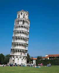
One of the world’s greatest attractions is actually a result of an engineering error. For over 800 years, the leaning tower of Pisa continues to draw worldwide attention and is a popular destination for tourists. Construction began in 1173 on an unstable foundation that comprised of mud, sand and clay. When engineers got to the third floor, the tower began to sink into the soft soil and lean on one side. They tried to fix the problem by making the columns and arches of the third story on the sinking northern side slightly taller. However, construction halted due to political unrest and only resumed a century later. The tower was closed in 1990 for safety reasons and millions of dollars were poured in to stabilize the structure and set it back to the position it had in 1838. Engineers added cables to stabilize the structure, then excavated under the tower and added trusses and counterweights.

Tacoma Narrows Bridge

Known as the “Galloping Gertie”, the original Tacoma Narrows Bridge was opened in July 1940 and at the time it was the third longest suspension bridge in the world. Its nickname was derived from the bridge’s sensitivity to high winds, causing it to sway and vibrate. Just four months after opening, the structure collapsed though its only fatality was a black Cocker Spaniel. Engineers failed to account for the aerodynamic forces within the location, especially during periods of strong winds. Thus the bridge was vulnerable to vibrations generated by wind. A replacement bridge was constructed ten years later, after the end of the Second World War. The remains of the original bridge remain at the bottom of Puget Sound, where they form one of the largest man-made reefs in the world.

Chernobyl Nuclear Power Plant

On 26 April 1986, a structurally unsound reactor in the Chernobyl Nuclear Power Plant, located in Ukraine, exploded. It was the worst nuclear power plant disaster in history, resulting in a severe nuclear meltdown. Highly radioactive materials were discharged into the atmosphere and over an extensive geographical region following the explosion. It spread to as far as Italy and to date over 500,000 deaths have been linked to this catastrophe. By May, about 116,000 people that had been living within a 30-kilometre radius had been evacuated and later relocated to safer regions. The accident was caused by a flawed reactor design that was operated with inadequately trained personnel and poor safety regulations.

New Orleans Canal and Levee System

In 2005 Hurricane Katrina hit New Orleans, devastating the city and flooding about 80 percent of the region, killing thousands and displacing several families. The U.S. Army Corps of Engineers were found liable for this devastation which was compounded by an antiquated levee and canal system that protected the city. The levees failed because they were built in a disjointed fashion, were inconsistent in quality, materials and design and outdated data was used that left gaps exploited by the storm. Additionally, engineers did not take into account the poor soil quality underneath New Orleans. Since then the U.S. government has spent more than $15 billion to upgrade the system.

Deepwater Horizon Spill

One of the worst environmental disasters in U.S. history, the Deepwater Horizon occurred in April 2010 after an explosion tore through a British Petroleum drilling rig. 11 crew members were killed and it is estimated that 180 million gallons of oil was released into the gulf. Over 8,000 animals were reported dead just 6 months after the spill and 16,000 total miles of coastline were affected, including the coasts of Texas, Louisiana, Mississippi, Alabama, and Florida. Mechanical failure as well as human error led to this colossal catastrophe. The engineers repeatedly ignored the well’s orneriness and chose to take quicker, cheaper and ultimately more dangerous actions that eventually led to the total well blowout.

Space Shuttle Challenger

Just a few seconds after the space shuttle challenger was launched in January 1986, it broke apart and killed everyone aboard. It resulted due to the failure of the solid rocket booster O-rings to seal properly, allowing hot combustion gases to leak from the side of the booster and burn through the external fuel tank. Though the problems with the O-rings had been known for nine years, engineers continued to ignore it as they assumed safety was ensured with the presence of the second ring. Eager to launch the shuttle, NASA managers also ignored warnings from engineers that low temperatures could exacerbate the problem.

Banqiao Reservoir Dam

Built in the early 1950s as party of a huge project to control flooding and produce electricity in central China, the Banqiao Reservoir Dam could hold back almost 500 million cubic meters of water. A hydrologist called Chen Xing warned that overbuilding of dams (over 100 were built in that period) and reservoirs could raise the water table in Henan beyond safe levels and lead to disaster. Furthermore, the dam was only built with 5 sluice gates when Xing warned that it needed at least 12. In August 1975, Typhoon Nina dropped more than a year’s worth of rain in just 24 hours and the dam failed. It released the equivalent of 280,000 Olympic-sized swimming pools, taking with it entire towns and killing as many as 171,000.

The Boston Molasses Disaster

Towering over Boston’s North End, construction ended on a massive molasses tank that stood 50 feet tall, 90 feet in diameter, and held more than 2 million gallons of molasses. The tank would help sate the USA’s appetite for industrial alcohol, largely for use in the munitions business. However, in their haste to make a profit, the owners overlooked the wisdom in hiring skilled engineers and instead sought out a man who was unable to read blueprints or even order a simple stress test. As a result, the tank exploded without warning and caused a wave of molasses and debris to travel down the street at 35 miles per hour. At 25 feet high, it ripped buildings off their foundations, killed 21 people and injured 150 others.

PREPARATION OF BAR BENDING SCHEDULE

Bar bending schedule (or schedule of bars) is a list of reinforcement bars, a given RCC work item, and is presented in a tabular form for easy visual reference. This table summarizes all the needed particulars of bars – diameter, shape of bending, length of each bent and straight portions, angles of bending, total length of each bar, and number of each type of bar. This information is a great help in preparing an estimate of quantities.

 The below illustration depicts the shape and proportions of hooks and bends in the reinforcement bars – these are standard proportions that are adhered to:

(a) Length of one hook = (4d ) + [(4d+ d )] – where, (4d+ d ) refers to the curved portion = 9d.
(b) The additional length (la) that is introduced in the simple, straight end-to-end length of a reinforcement bar due to being bent up at say 30o to 60o, but it is generally 45o) = l1 – l2 = la
Where,


Giving different values to clip_image005 respectively), we get different values of la, as tabulated below:
The below table presents the procedure to arrive at the length of hooks and the total length of a given steel reinforcement.Typical Bar Bending Schedule

Introduction to Finite Element Analysis

Finite Element Analysis (FEA) was first developed in 1943 by R. Courant, who utilized the Ritz method of numerical analysis and minimization of variational calculus to obtain approximate solutions to vibration systems. Shortly thereafter, a paper published in 1956 by M. J. Turner, R. W. Clough, H. C. Martin, and L. J. Topp established a broader definition of numerical analysis. The paper centered on the "stiffness and deflection of complex structures". 
 
By the early 70's, FEA was limited to expensive mainframe computers generally owned by the aeronautics, automotive, defense, and nuclear industries. Since the rapid decline in the cost of computers and the phenomenal increase in computing power, FEA has been developed to an incredible precision. Present day supercomputers are now able to produce accurate results for all kinds of parameters.

What is Finite Element Analysis?
FEA consists of a computer model of a material or design that is stressed and analyzed for specific results. It is used in new product design, and existing product refinement. A company is able to verify a proposed design will be able to perform to the client's specifications prior to manufacturing or construction.

There are generally two types of analysis that are used in industry: 2-D modeling, and 3-D modeling. While 2-D modeling conserves simplicity and allows the analysis to be run on a relatively normal computer, it tends to yield less accurate results. 3-D modeling, however, produces more accurate results while sacrificing the ability to run on all but the fastest computers effectively. 
How Does Finite Element Analysis Work? 
FEA uses a complex system of points called nodes which make a grid called a mesh . This mesh is programmed to contain the material and structural properties which define how the structure will react to certain loading conditions. Nodes are assigned at a certain density throughout the material depending on the anticipated stress levels of a particular area. Regions which will receive large amounts of stress usually have a higher node density than those which experience little or no stress. Points of interest may consist of: fracture point of previously tested material, fillets, corners, complex detail, and high stress areas. The mesh acts like a spider web in that from each node, there extends a mesh element to each of the adjacent nodes. This web of vectors is what carries the material properties to the object, creating many elements. 

Types of Engineering Analysis
 
Structural analysis consists of linear and non-linear models. Linear models use simple parameters and assume that the material is not plastically deformed. Non-linear models consist of stressing the material past its elastic capabilities. The stresses in the material then vary with the amount of deformation as in Figure 4.
Vibrational analysis is used to test a material against random vibrations, shock, and impact. Each of these incidences may act on the natural vibrational frequency of the material which, in turn, may cause resonance and subsequent failure.
Fatigue analysis helps designers to predict the life of a material or structure by showing the effects of cyclic loading on the specimen. Such analysis can show the areas where crack propagation is most likely to occur. Failure due to fatigue may also show the damage tolerance of the material (Figure 5).
Heat Transfer analysis models the conductivity or thermal fluid dynamics of the material or structure (Figure 1). This may consist of a steady-state or transient transfer. Steady-state transfer refers to constant thermoproperties in the material that yield linear heat diffusion.


Results of Finite Element Analysis
FEA has become a solution to the task of predicting failure due to unknown stresses by showing problem areas in a material and allowing designers to see all of the theoretical stresses within. This method of product design and testing is far superior to the manufacturing costs which would accrue if each sample was actually built and tested.

Wednesday 18 November 2015

KENYA FOOD SECURITY

First lets gets the stats as they are:

-In 2008, an estimated 1.3 million people in rural areas and 3.5 – 4 million in urban areas were food insecure.
-October to December 2014 short rains were well below average, which caused food insecurity in the Southeast, the coastal lowlands, and pastoral areas. Over the next several months, the food insecure population rose to over 1.5 million people.
-2015. Under the forecast of a strong El Niño episode, which is likely to continue into the first months of next year, rains are expected at above-average levels until December, thus benefiting crops. However, exceptionally heavy rains could increase the risk of flash floods in low-lying areas, negatively affecting standing crops, livestock and destroying rural infrastructures.
-By August 2015, 1.1 million people were acutely food insecure. However this was not inclusive of post El nino crises. Agricultural production is expected to dwindle and comes a corresponding increase in food shortage

 My views: Food Insecurity is a problem purposely neglected by leaders 

Agriculture is the backbone of the Kenyan economy, and improving private, small-scale farms is essential to a broad-based, poverty-reduction strategy. Overall, 75 percent of Kenya’s population derives at least part of their livelihoods from agriculture, including livestock and pastoral activities. Agriculture accounts for more than half of Kenya’s GDP  
Kenya’s agricultural sector is characterised by small-scale farms that mainly produce to meet the requirements of their own individual households. As a result of rapid population growth, the impacts of climate change, and land and water shortages, natural resources are being overexploited and the country’s agricultural and food industries are facing major challenges.

Under the Vision 2030, the Government has identified the following seven flagship
projects for implementation during the next 5 years:
1.Agricultural policy reforms
2.Three-tiered fertilizer cost reduction
3.Branding Kenya farm produce
4.Establishment of livestock disease free zones and processing facilities
5.Creation of publicly accessible land registries
6.Development of agricultural land use master plan
7.Development of irrigation schemes. 

however  this visions are more achievable on the present turf and can give the present government a better image of having eradicated food insecurity. Over reliance on maize and maize production should be corrected. Rain water harvesting should be adopted especially in areas with high surface run offs.

It is said that currently we are Facing a "problem" of el Niño. But instead of working tirelessly to discard the water, efforts should be made to trap this water for irrigation and other uses.
I believe a country which is food secure should be on the right path to achieve vision 2030. However on paper it doesn’t look that much of an issue but on ground food insecurity is estimated to affect over 2 million people.
But if Kenya was food secure, our leaders would have one less thing to use for their selfish gains (-:


Leonardo da Vinci

Leonardo da Vinci, ( Italian: “Leonardo from Vinci”)  (born April 15, 1452, Anchiano, near Vinci, Republic of Florence [Italy]—died May 2, 1519, Cloux [now Clos-Lucé], France), Italian painter, draftsman, sculptor, architect, and engineer whose genius, perhaps more than that of any other figure, epitomized the Renaissance humanist ideal. His Last Supper (1495–98) and Mona Lisa (c. 1503–06) are among the most widely popular and influential paintings of the Renaissance. His notebooks reveal a spirit of scientific inquiry and a mechanical inventiveness that were centuries ahead of their time.

However among others of  da Vinci notable works included a design of a fortress:

 BUILDING AND ARCHITECTURE
Cesare Borgian hired da Vinci to design a fortress. As this design, along with his work on the Lombard canal system, both clearly demonstrate, his approach was highlighted by a phenomenal emphasis on careful scientific observation and a thorough understanding of the strength of materials. 
 Back then strength of materials was not a subject having a lot of information 
Applying for service in a letter to Ludovico Sforza, Leonardo described himself as an experienced architect, military engineer, and hydraulic engineer; indeed, he was concerned with architectural matters all his life. But his effectiveness was essentially limited to the role of an adviser. Only once—in the competition for the cupola of the Milan cathedral (1487–90)—did he actually consider personal participation, but he gave up this idea when the model he had submitted was returned to him. In other instances, his claim to being a practicing architect was based on sketches for representative secular buildings: for the palace of a Milanese nobleman (about 1490), for the villa of the French governor in Milan (1507–08), and for the Medici residence in Florence (1515). Finally, there was his big project for the palace and garden of Romorantin in France (1517–19). Especially in this last project, Leonardo’s pencil sketches clearly reveal his mastery of technical as well as artistic architectural problems; the view in perspective gives an idea of the magnificence of the site.
But what really characterizes and immortalized Leonardo’s architectural studies is their comprehensiveness; they range far afield and embrace every type of building problem of his time and even involve urban planning. Furthermore, there frequently appears evidence of Leonardo’s impulse to teach: he wanted to collect his writings on this theme in a theory of architecture. This treatise on architecture—the initial lines of which are in Codex B in the Institut de France in Paris, a model book of the types of sacred and profane buildings—was to deal with the entire field of architecture as well as with the theories of forms and construction and was to include such items as urbanism, sacred and profane buildings, and a compendium of important individual elements (for example, domes, steps, portals, and windows).
In the fullness and richness of their ideas, Leonardo’s architectural studies offer an unusually wide-ranging insight into the architectural achievements of his epoch. Like a seismograph, his observations sensitively register all themes and problems. For almost 20 years he was associated with Bramante at the court of Milan and again met him in Rome in 1513–14; he was closely associated with other distinguished architects, such as Francesco di Giorgio, Giuliano da Sangallo, Giovanni Antonio Amadeo, and Luca Fancelli. Thus, he was brought in closest touch with all of the most-significant building undertakings of the time. Since Leonardo’s architectural drawings extend over his whole life, they span precisely that developmentally crucial period—from the 1480s to the second decade of the 16th century—in which the principles of the High Renaissance style were formulated and came to maturity. That this genetic process can be followed in the ideas of one of the greatest men of the period lends Leonardo’s studies their distinctive artistic value and their outstanding historical significance.

Hydraulics


back
Leonardo worked continuously and with originality on his study of water, and many drawings and observations are to be found scattered throughout the various notebooks. The idea of drawing all this long experience together in a treatise occurred to him several times, but the attempt came to an end almost as soon as it was begun. His interest in water probably began when he was a boy, and in Verocchio's studio in Florence he had some experience with fountains, but it was during his time in Lombardy that he discovered possible applications that were unknown in Tuscany. Advanced canal building had long existed in Lombardy, for hydrographical reasons, and as the Duke's engineer, Leonardo had to apply himself to the fundamental problem of water since not only agriculture but also the working of machines and mills depended on its being properly regulated.

By carefully observing the flowing of rivers, he drew a number of conclusions about movement, erosion, and currents on the surface and below, often with the assistance of little wooden or glass models through which he made water flow. The results of these experiments were then applied to the practical problems of canal building, and many drawings of bulkheads, portholes and locks with movable gates are preserved in his notebooks. Leonardo's mind then turned to the much greater project of intervening in nature by deviating the River Arno and building a large, navigable canal which would connect Florence to the sea, through the area of Prato, Pistoia and Serravalle, and provide the longed-for access to the Tyrrhenian Sea. He devised further ambitious hydraulic schemes for the Veneto, where he saw the possibility of flooding the Isonzo valley in the event of a Turkish invasion, and for Lazio, where Pope Leo X consulted him about draining the Pontine Marshes.

Fascinated by the idea of enabling men to move on and under the water, he designed buoys and breathing equipment, as well as considering the possibility of making boats move faster, with an improved hull in the shape of a fish or by machines operating paddles from within the vessel. The requirements of war persuaded him of the usefulness of a vessel with a double hull to protect it from the kind of damage he proposed to inflict on enemy ships, with men in diving suits equipped with screw devices breaking the keel and stealthily anchoring the ship to the bottom of the sea. Supplying city centres as well as the need to drain basins and marshland involved Leonardo in improving machines and pumps which had been known since ancient times. The Archimedean screw and water wheels fill the notebooks of Francesco di Giorgio Martini and other engineers of the time but, with Leonardo, they attained a graphic and functional perfection unknown elsewhere.
 

ROMAN ROADS AND HIGHWAYS

Standard Roman roads consisted of a metalled surface (ie gravel or pebbles) on a solid foundation of earth or stone.

A simple yet technologically advanced plan was in place and implemented for the construction of each road.

Where possible, roads were built in the straightest line possible, only avoiding major terrain obstacles where it made practical sense. A Roman road was a multi-layered architectural achievement, but the construction process was fairly simple to define.
First the two parallel trenches were built on either side of the planned road, with the resulting earthworks, stone, etc., being dumped and built up in the space between the two ditches. The Agger, as this was called, could be up to 6 ft. (1.8 m) high and 50 ft. (15 m) wide. Alternatively it could be very slight or almost non-existent as was the case with most minor roads.
Next, the diggers would make a shallow 8 to 10 foot wide depression down the length of the agger, and line the edges with kerb stones to hold the entire construction in place. The bottom of this depression would then be lined with a series of stone fillers. 6 to 8 inch stones would form the foundation layer, with fist sized stones placed on top. In early roads the remaining gap would then be filled in with course sand to fill between the stones and to cover them by approximately 1 ft.

Later roads may have used Roman volcanic concrete to mix the entire mixture together making the whole structure more solid. The road surface was then laid down using large, tight fitting, flat stones that could be found and transported locally. These larger surface stones would be cut to fit when possible to make the surface as smooth and seamless as possible.
Bridle paths were then dug and smoothed, leaving the earth unpaved for horse travel. The roads were built for infantry, and it was easier on horse hooves to walk alongside the stone roads. Though the Romans did use horseshoes, they were tied on to the hooves, not nailed, making them unstable. Additionally, during the construction, forests and obstacles on either side of the road could be cleared to a considerable distance to guard against ambush attempts.

The Roman Road Network

The Romans did not invent roads, of course, but, as in so many other fields, they took an idea which went back as far as the Bronze Age and extended that concept, daring to squeeze from it the fullest possible potential. The first and most famous great Roman road was the Via Appia (or Appian Way). Constructed from 312 BCE and covering 196 km (132 Roman miles), it linked Rome to Capua in as straight a line as possible and was known to the Romans as the Regina viarum or 'Queen of Roads'. Much like a modern highway, it did not go through less important towns along the way, and it largely ignored geographical obstacles. For example, the impressive 90 km stretch from Rome to Terracina was built in a single straight line. The road would later be extended all the way to Brundisium and thus reach 569 km in length (385 Roman miles).

Other famous roads in Italy were the Via Flaminia which went from Rome to Fanum (Fano), the Via Aemilia from Placentia to Augusta Praetoria (Aosta), the Via Postumia from Aquileia to Genua (Genoa), the Via Popillia from Ariminum (Rimini) to Padova in the north and from Capua to Rheghium (Reggio Calabria) in the south, and many more besides, all with extensions made over time. The roads became so famous that they even gave their names to places and regions. The network gradually spread across the empire from Britain to Syria, and certain roads became as well-known and well-travelled as those around Rome itself. For example, the Via Domitia (begun in 116 BCE) went from the French Alps to the Pyrenees and was invaluable for troop movements in the campaigns in Spain. There was also the Via Egnatia (begun in the mid-second century BCE), which crossed the Balkan Peninsula and ended at Byzantium, making it a vital land route between the western and eastern parts of the empire.

Battlefield Surgery

The Romans are known to have had some knowledge of the internal workings of human bodies, particularly through the work of Galen. However, historians question whether they performed internal surgical operations. Through their work with gladiators and wounded soldiers, Roman doctors became experts at practical first aid and external surgery.

THE first evidence that doctors in ancient Rome were able to carry out successful amputations has been uncovered by anthropologists.
A 2nd Century thigh bone found in a cemetery near Rome clearly shows the serrated marks of a surgeon's saw. The amputee was a tall man who must have survived for months or even years after his operation, because the bone had started to heal. This suggests that the surgeons were skilled enough to fashion a flap of tissue to sew over the amputated end, protecting it from the air.
Roberto Macchiarelli, of the Museo Preistorico e Etnografico L Pigorini in Rome, whose team uncovered the bone, said that the man was probably from the middle or upper middle classes to be able to afford the cost of an operation. The bone was found mixed with a number of skeletal remains in a large monumental tomb at the Isola Sacra cemetery.
David Weaver, an expert in ancient bones who analysed the femur at Wake Forest University, North Carolina, thinks that the man possibly wore a wooden leg, because of the way the cut end had worn. The 1st Century Roman writer Celsus refers to the practice of surgical amputations and there are instruments in museum collections capable of carrying out such operations.
Mr Weaver said: "But we have never seen an amputation before. This confirms what we suspected, that Roman doctors were able to do this." He believes that ancient Roman doctors were at least as skilful as those during the American civil war who carried out battlefield amputations with a similar level of expertise.
The femur also shows signs of a painful infection, pyogenic osteomyelitis, which either led to the amputation in the first place or set in afterwards. Important families would have a large ornate grave constructed, in which the bodies of relatives and freed slaves would be laid to rest alongside their masters. Unfortunately, the quantity of bones mixed together have defeated efforts to reunite the femur with the rest of its skeleton, to get a better idea of the person it belonged to.
By coincidence, the tomb lies close to another imposing monument to Ulpius Amerimnus, who was a famous doctor of medicine, and to his Greek wife, Scribonia Attice. The couple's tomb bears two bas-reliefs, one showing surgical cutting tools and another showing Scribonia acting as a midwife. Mr Macchiarelli said: "We can't say for sure that this man was contemporaneous with Ulpius or that there was a link between the two, but symbolically it seems important."
Isola Sacra lies in the city of Portus, the main port of Rome, which was built by the emperor Trajan to accommodate the huge number of ships plying to and fro from the imperial capital. Analysis of the oxygen composition of the bone remains show that its population was extremely diverse. Hundreds of thousands lived there, slaves from Nubia jostling with immigrants from England.
Mr Macchiarelli said: "It was a New York-like city where you could find very rich and very poor people living side by side. Little is known about the physical remains of ancient Romans because the main imperial graveyards were excavated in the 19th century before science had developed sufficiently to analyse the bones.
Now they have been concreted over and lie inaccessible, several metres below the modern city. The graves of Isola Sacra have survived because the cemetery lies outside Rome, along a narrow road between Portus and Ostia, the original Roman port.